In Part 1 of the blog series, we covered the setup and configuration necessary for Snowflake integration using the Snowflake REST API with a custom connector. The API response isn’t directly usable in Power Apps if the action is directly called within Power Apps instead of Power Automate flow leveraging Data operations (Select) connector. In this blog post, let’s explore how to manipulate the Snowflake API response using custom code with C# to transform the response payload. Find below the response from the API, without transformation, appears as follows for the SQL statement select name, age from rockers_table.
Revise the custom connector created in the previous blog post by clicking “Code” to add the C# code for transforming the data. The required response to the SQL query is under the key named data, and the value before and after transformation, is shown below.
The following C# code transforms the response in the required format:
public class script: ScriptBase
{
public override async Task < HttpResponseMessage > ExecuteAsync()
{
    // Check which operation ID was used
    if (this.Context.OperationId == "GETSFData")
    {
        return await this.ManipulateResponse().ConfigureAwait(false);
    }

    // Handle an invalid operation ID
    HttpResponseMessage response = new HttpResponseMessage(
        HttpStatusCode.BadRequest
    );
    response.Content = CreateJsonContent(
        $"Unknown operation ID '{this.Context.OperationId}'"
    );
    return response;
}

private async Task < HttpResponseMessage > ManipulateResponse()
{
    // Use the context to forward/send an HTTP request
    HttpResponseMessage response = await this.Context.SendAsync(
        this.Context.Request,
        this.CancellationToken
    ).ConfigureAwait(continueOnCapturedContext: false);

    // Do the transformation if the response was successful
    if (response.IsSuccessStatusCode)
    {
        var responseString = await response.Content.ReadAsStringAsync().ConfigureAwait(
        continueOnCapturedContext: false
        );

        // Example case: response string is some JSON object
        var result = JObject.Parse(responseString);

        // Initialize an empty array to store the new formatted data
        var newDataArray = new JArray();

        // Iterate over the original "data" array
        foreach (var item in result["data"])
        {
            // Create a new JObject for each inner array
            var newItem = new JObject
            {
                ["Name"] = item[0], // Set the "Name" property
                ["Age"] = item[1]   // Set the "Age" property
            };

            // Add the new JObject to the new data array
            newDataArray.Add(newItem);
        }

        // Create a new JObject to hold the formatted data
        var newResult = new JObject
        {
            ["data"] = newDataArray // Set the "data" property to the new formatted data array
        };

        response.Content = CreateJsonContent(newResult.ToString());
    }
     return response;
}
}
In the Power Apps, the PowerFX to execute the SQL query is
Set(sfData, 'CC-SnowFlake-AWS'.GETSFData({database: "HOL_DB",role:"PUBLIC",schema:"PUBLIC",statement:"select name, age from rockers_table;",warehouse:"HOL_WH"}))
To display the value in the gallery control, the Power FX is sfData.data
The scenario provided above serves as just one example of data transformation. While Power Automate offers data operations that can assist in such tasks, the method described above facilitates using the connector action directly within Power Apps. Hope you have found this informational & thanks for reading. If you are visiting my blog for the first time, please do look at my other blogposts.
Do you like this article?
Subscribe to my blog with your email address using the widget on the right side or on the bottom of this page to have new articles sent directly to your inbox the moment I publish them.
In today’s data-driven world, businesses rely on integration between their data sources and analysis platforms to derive insights and make informed decisions. One such powerful combination is leveraging Snowflake, a leading cloud-based data warehousing platform, alongside Microsoft Power Platform. In this blog series, we’ll delve into the options of integrating Snowflake data sources into Power Platform, exploring both custom and out-of-the-box connector options. In Part 1, our focus will be on setting up and configuring Snowflake, followed by creating a custom connector that leverages Snowflake’s SQL REST API. This connector facilitates the connection between Snowflake and the Power Platform services such Power Apps and Power Automate.
Pre-requisites:
Snowflake account with Account Admin access: Snowflake offers a 30-day trial, granting full access to explore its capabilities. You can select either Azure/AWS/GCP
Entra ID access (Global Admin or Privileged Administrator Role) to create App registration and grant Admin consent: Ensure you have Entra ID access to enable the creation of App registrations and to grant Admin consent for necessary permissions.
Power Platform Administrator Role: To make adjustments to allow custom connector endpoints for Snowflake identifier URL, especially in cases where endpoints are blocked by the tenant scoped DLP policy.
Maker or System Administrator access in a Power Platform Environment: Access privileges should include Maker or System Administrator rights within your Power Platform environment to register custom connector.
Power Apps premium license: A Power Apps premium license is required to use a custom connectors in a Power Apps or a Cloud flow.
This blog post is divided into the following sections:
Creation of Entra ID Apps.
Setup Snowflake Environment.
Creation of a custom connector & DLP Policy Update.
Creation of Entra ID Apps:
There are two app registrations required to facilitate the API access through Microsoft Entra ID, where one would represent the Snowflake OAuth resource and the other would represent the OAuth client application which would be in this case the custom connector
Section 1 – Registering an Application in Microsoft Entra ID for Snowflake OAuth resource:
In the Entra ID portal, navigate to App registrations and click + New registration. Enter a name, such as Snowflake OAuth resource, and proceed by clicking the Register button, leaving all settings as default.
Under the Manage section in the side menu, select Expose an API. Set the Application ID URI with the default value and remember to copy this value for future use. This will be known as external_oauth_audience_list in the section Setup and configuration in Snowflake
Click on the Add a scope button to access the panel. The Snowflake Role Public is added as an OAuth scope for OAuth flows where the Snowflake OAuth client acts on behalf of a user from the custom connector. If there is a custom Snowflake role, it should be added as a scope instead of ‘Public’:
Enter a new Scope name as session:scope:PUBLIC
Set Admin consent display name to Account Admin
Provide Admin consent description as “Can Administer the Snowflake account”
Ensure the Enabled scope state is selected.
Complete the process by selecting the Add scope button to create the scope.
Section 2 – Registering an Application in Microsoft Entra ID for Snowflake OAuth client:
In the Entra ID portal, navigate to App registrations and click + New registration. Enter a name, such as Snowflake OAuth client, and proceed by clicking the Register button, leaving all settings as default.
Retrieve the Client ID, Tenant Id from the Overview section of the Entra ID app and generate a secret through the Certificates & secrets under the Manage blade. Once the secret is successfully created, copy its value for use in configuring the custom connector OAuth Authentication.
In the API permissions section under the Manage blade, click + Add a permission and search for Snowflake OAuth resource, the application created previously.
Select the Delegated permission session:scope:PUBLIC defined in the previous section as shown below, and grant Admin consent.
Everything is configured in Entra ID. Now, let’s move on to Snowflake to set up the necessary components for this integration to function.
Let’s head in to the Snowflake instance as an Account Admin. Here, you’ll create a
Create Database with sample data & grant roles
Set up security integration
Create a user in Snowflake synchronized with the Entra ID user
Log in to the Snowflake instance to copy the Identifier URL as shown below. This URL will be used in the custom connector to access the Snowflake REST API.
Create a SQL Worksheet as shown below and execute the following script to set up the Snowflake environment by creating a warehouse, database, and table named ‘rockers_table’. Sample data is inserted into the table, and permissions are granted to the ‘public’ role for accessing and updating the table:
-- Switch to the 'accountadmin' role
use role accountadmin;
-- Create the HOL_WH warehouse with size 'X-SMALL'
CREATE OR REPLACE WAREHOUSE HOL_WH WITH WAREHOUSE_SIZE='X-SMALL';
-- Create the HOL_DB database
CREATE OR REPLACE DATABASE HOL_DB;
-- Grant usage on the warehouse HOL_WH to the role 'public'
GRANT USAGE ON WAREHOUSE hol_wh TO ROLE public;
-- Grant usage on the database HOL_DB to the role 'public'
grant usage on database hol_db to role public;
-- Grant usage on the schema HOL_DB.PUBLIC to the role 'public'
grant usage on schema hol_db.public to role public;
use role accountadmin;
-- Switch to the HOL_DB database
use database HOL_DB;
use warehouse HOL_WH;
-- Create the 'rockers_table' table
CREATE TABLE rockers_table (
  id INT,
  name VARCHAR(50),
  age INT
);
-- Insert data into the 'rockers_table' table
INSERT INTO rockers_table (id, name, age)
VALUES (1, 'Jimi Hendrix', 27),
       (2, 'Janis Joplin', 27),
       (3, 'Elvis Presley', 42),
       (4, 'Freddie Mercury', 45),
       (5, 'Whitney Houston', 48),
       (6, 'Michael Jackson', 50),
       (10, 'John Lennon', 40);
-- Grant select and update permissions on the 'rockers_table' table to the role 'public'
grant select, update on table hol_db.public.rockers_table to role public;
Set up security integration:
Let’s proceed to create the Security integration, which is a Snowflake object that establishes an interface between Snowflake and Entra ID. This integration is a prerequisite for enabling Entra OAuth authentication in the custom connector. Execute the following script:
Replace the tenantid in ‘external_oauth_issuer’ and ‘external_oauth_jws_keys_url’, and the Application ID URI in ‘external_oauth_audience_list’. These values should be copied from sections 1 and 2 of the Entra ID app creation process written above.
Create a user in Snowflake synchronized with the Entra ID user:
We’ll create a user in Snowflake that mirrors the Entra ID user upn as created in the security integration. In the User & Roles section under Admin, click + User. The login name should be the UPN (User Principal Name) from Entra ID/AD. Once the required details are entered, proceed to click on Create User.
Creation of a custom connector & DLP Policy Update:
The custom connector serves as a wrapper around the Snowflake REST API, facilitating communication between Power Apps or Power Automate and the API. To create this connector, navigate to Custom connectors in the Power Apps/Power Automate maker portal, then click on + New custom connector and select Create from blank. Enter the connector name, and on the subsequent screen, enter the Snowflake Identifier URL in the Host field and some description about the connector.
Now click Security on the right bottom corner or from the Tab to enter the Entra ID application information copied from the App registration Snowflake OAuth Client for the OAuth 2.0 authentication type. Under the section OAuth 2.0
Change the Identity provider to Azure Active Directory
Enter the Client id & Client secret copied from the Section 2 of the Entra ID app registration Snowflake OAuth Client
Enter the Resource URL as api://applicationIDURI copied from the Section 1 of the Entra ID app registration Snowflake OAuth Resource
Enter the Scope as session:scope:PUBLIC based on the permissions you have added. Leave a space between each permission if there are multiple permissions
The connector is now prepared to add actions based on the Snowflake REST API endpoints. Snowflake’s REST API offers functionalities such as submitting SQL statements, checking execution statuses, cancelling executions, and fetching query results concurrently. This blog post will primarily concentrate on integrating with the API to submit SQL statements. For more guidelines, it’s recommended to look at the Snowflake REST API documentation for best practices.
Let’s proceed to add an action for submitting a SQL statement. Navigate to Definitions and select + New action. Once you’ve filled in the Summary, Description, and Operation ID (e.g., GETSFData), click on + Import from sample under the Request section, and input the following details:
{
"statement": "select name, age from rockers_table;",
"timeout": 60,
"database": "HOL_DB",
"schema": "PUBLIC",
"warehouse": "HOL_WH",
"role": "PUBLIC"
}
Click Import & Update connector then proceed to click the Test tab and create a New connection. In the event of encountering DLP error message indicating that connection creation has been blocked by Data Loss Prevention (DLP) policy. Add the Snowflake Identifier URL as a connector pattern allowed in the Business/Non Business category of the DLP policy.
VOILA, everything is set up. You can now test the action to execute a SQL statement to retrieve data from the rockers_table as shown below:
The request body for updating an existing item is
{
"statement": "UPDATE rockers_table SET Name = 'Mohamed Ashiq' WHERE ID = '1';",
"timeout": 60,
"database": "HOL_DB",
"schema": "PUBLIC",
"warehouse": "HOL_WH",
"role": "PUBLIC"
}
Summary:
In the next part of the blog series, we’ll explore how to manipulate the response from the connector action. This involves adding C# code in the custom connector to facilitate the display in Power Apps gallery control without using a Power Automate flow. Hope you have found this informational & thanks for reading. If you are visiting my blog for the first time, please do look at my other blogposts.
Do you like this article?
Subscribe to my blog with your email address using the widget on the right side or on the bottom of this page to have new articles sent directly to your inbox the moment I publish them.
Capabilities like text-to-speech (TTS) and audio playback can take your applications to new heights of user engagement and accessibility. In this blog post, we’ll look at integrating text-to-speech and audio playback functionalities into Power Apps using Power Automate and Azure Speech Services. Whether you’re looking to provide dynamic narration, streamline communication, or enhance accessibility, this post will walk you through the steps to integrate TTS capabilities into your Power Apps projects.
Prerequisites:
Before you begin, ensure that you have the following prerequisites in place:
Maker role in Power Platform environment
Premium License – HTTP Connector
Azure Subscription Access
Azure Speech services – Text to speech
Creating Speech Services in Azure for Text to Speech:
Azure provides Speech Services that enable developers to integrate advanced speech capabilities into their applications, including Text to Speech (TTS). With Azure Speech Services, you can convert text into speech in various languages and voices.
Step 1: Create the resource Speech services in the Azure Portal
Step 2: Copy the Key from the Keys and Endpoint section within the Resource Management blade. This Key is used for authentication when making requests to the Speech service APIs, enabling text-to-speech conversion in the Power Automate flow through the HTTP connector.
Step 3: Go to the Speech Studio to choose a voice from the gallery provided in Text to Speech section. Alternatively, you can create a custom voice using your own audio recordings. The Speech Studio can also be accessed from the Overview section of the Speech service in the Azure portal.
Power Automate Flow to convert the text to speech:
The Power Automate serves as a tool in orchestrating the integration between Power Apps and Azure Speech Services, enabling communication between the components. Create an Instant Power Automate flow with the trigger “PowerApps (V2)” either from the Power Automate portal or directly from the Power Apps maker interface. Add a text input varTextInput as shown below to send the text from the Power Apps
The next step involves converting the text to speech/audio utilizing the Text to Speech REST API through the HTTP connector action. Add the HTTP action with request details as below
Method: POST
URI: Depending on the region where you’ve created the Azure Speech resource, select the corresponding Rest API endpoint from the list in the Microsoft documentation. For instance, if the Speech Service resource is created in West Europe, the URL will be:
In the request body, add the varTextInput included to the Power Apps trigger. I have added the voice en-US-JennyNeural, you can select it from the voice gallery as discussed above.
Next, add a Compose action to convert the audio generated from the HTTP action into base64 format. This will serve as the text output passed in the Respond to a PowerApp or flow action, as shown below:
Let’s develop the app for the text narration feature, where users can input text to be converted into audio using the Power Automate flow created earlier. On the Canvas, add a Text Input control for entering the desired text, an Audio control to play the audio generated from the Azure text-to-speech service, and a button to trigger the Power Automate flow. Make sure the flow is added to the Power Apps. Add the following code to the OnSelect property of the button
// Reset the Audio1 control to its default state, clearing any previous audio.
Reset(Audio1);

// Run the TexttoSpeechFlow Power Automate flow, passing the text from TextInput1 as input.
// Store the result (converted audio) in the varconvertedAudio variable.
Set(varconvertedAudio, TexttoSpeechFlow.Run(TextInput1.Text));

// Set the playAudioContent variable to false, ensuring that any previous audio playback is stopped.
Set(playAudioContent, false);

// Set the playAudioContent variable to true, triggering playback of the newly converted audio.
Set(playAudioContent, true);
The variable playAudioContent will be used in Audio control Star property to play the audio automatically
The Media property of the Audio control should have the following formula, depending on the output variable added in the ‘Respond to PowerApps or flow’ action of the Power Automate flow
The x-wav is the format of the generated audio from the Text to Speech REST API in the Power Automate flow which can be validated from the output of the HTTP action HTTP-TexttoSpeech
You are now ready to test your app.
Summary:
By combining the power of Power Automate and Azure Speech Services developers can quickly integrate text-to-speech and audio playback functionalities into their Power Apps. Hope you have found this informational & thanks for reading. If you are visiting my blog for the first time, please do look at my other blogposts.
Do you like this article?
Subscribe to my blog with your email address using the widget on the right side or on the bottom of this page to have new articles sent directly to your inbox the moment I publish them.
In both Part 1 and Part 2 of the blog series, I’ve covered the utilization of Managed Identities in Power Apps and Power Automate for secure access to Microsoft Graph API. This included a deep dive into setting up and configuring the Azure API Management service with the Microsoft Graph permissions for the managed identity. In Part 2, I’ve explored the process of exporting the API as a connector in Power Platform, securing it with API key authentication.
To enhance the security of the custom connector published from Azure API Management for Microsoft Graph APIs using Entra ID OAuth authentication instead of Subscription key, it is essential to create two Entra ID applications. One application should represent the API from API Management, while the other should represent the client application to be utilized in the Entra ID OAuth authentication for the custom connector.
Registering an Application in Microsoft Entra ID for API Representation:
In the Entra ID portal, navigate to App registrations and click + New registration. Enter a name, such as APIM PP Resource, and proceed by clicking the Register button, leaving all settings as default. This app represents the APIs added in the Azure API management instance.
Under the Manage section in the side menu, select Expose an API. Set the Application ID URI with the default value and remember to copy this value for future use.
Click on theAdd a scope button to access the Add a scope panel:
Enter a new Scope name as APIM.MSGraphAPI
Set Admin consent display name to APIM MSGraph API
Provide Admin consent description as “Grants access to the API in APIM.”
Ensure the Enabled scope state is selected.
Complete the process by selecting the Add scope button to create the scope.
Registering an Application in Microsoft Entra ID for Client Representation:
Create another Entra ID app to be used in the custom connector for securing with Entra ID OAuth Authentication. In the Entra ID portal, navigate to App registrations and click + New registration. Enter a name, such as APIM PP Client, and proceed by clicking the Register button, leaving all settings as default.
Retrieve the Client ID, Tenant Id from the Overview section of the Entra ID app and generate a secret through the Certificates & secrets under the Manage blade. Once the secret is successfully created, copy its value for use in configuring the custom connector OAuth Authentication.
Go to the Entra ID app APIM PP Resource created earlier. In the Manage section, click on Expose an API and then Add a client application by selecting + Add a client application in the popout panel. Enter the Client ID of the APIM PP Client app registered now. Select the authorized scope created in the previous section, then proceed by clicking Add Application. This ensures the application APIM PP Resource trusts the client application APIM PP Client and users should not be asked to consent when the client calls the APIs published API Management instance.
Note: If you prefer users/admins to provide consent for the permission while creating a connection for the custom connector, add the APIM.MSGraphAPI Scope to the APIM PP Client app, as shown below. In this scenario, the step mentioned in bullet no 2 becomes unnecessary.
Configuring Custom Connector Authentication to Entra ID OAuth:
Following the export of the API from the Azure API Management as a custom connector in Power Platform in Part 2 of this blog series, proceed to the Power Apps or Power Automate maker portal to edit the connector.
Access the custom connectors, locate the exported connector in the Power Platform Environment where the connector was exported from API Management
Within the Authentication type settings, originally set to API Key, click Edit, and modify it to OAuth 2.0.
Choose the Identity provider as Azure Active Directory. Enter the Client ID and Client secret obtained from the APIM PP Client app copied earlier. Set the resource URL to the Application ID URI generated from the APIM PP Resource app.
Click Update connector to generate a Redirect URL on the same screen—ensure to copy this URL.
Navigate to the APIM PP Client app in the Entra ID portal and add a Web Redirect URI, paste the copied Redirect URL.
Azure API Management: Configure JWT validation policy to Authorize requests from Custom connector:
The JWT validation policy pre-authorizes requests from the Power Platform Custom connector as it adds the layer of security to ensure that incoming access tokens are valid and meet specific criteria before the APIM starts processing requests to the added MS Graph API endpoints. The policy checks the value of the audience claim in an access token obtained from Microsoft Entra ID with in the custom connector. The audience claim typically specifies the intended recipient of the token, ensuring that the token is meant for the intended API.
By configuring the following JWT validation policy in the <inbound> policy section below the node <base />, you enforce the validation of the access token, and if the token is invalid, an error message is returned. Don’t forget to replace the TenantId and the required claims value to the client id of the app APIM PP Resource.
Note: If you attempt to establish the connection from the Test Tab and subsequently execute the action, you will encounter the following error “Access denied due to missing subscription key. Make sure to include subscription key when making requests to an API.
Creating a Product:
To enable the custom connector to generate tokens for API access from API Management, it’s necessary to associate the APIs with a Product that doesn’t require a subscription key. Follow these steps:
In the left navigation pane, go to Products and click on + Add.
Provide the Product Name, Description, uncheck the box Require subscription option, select the relevant API, and proceed to create the Product.
Testing the Custom connector:
Navigate to the Power Platform Maker portal and access the custom connector interface. Edit the connector to initiate the creation of a connection within the Test tab. Click on + New connection and click Create. Notably, you’ll observe that it doesn’t prompt for the API Subscription key, as discussed in the Part 2 of the article.
Once the connection is created, return to the edit mode of the custom connector to initiate testing of the actions. Navigate to the Test tab, where you can select the specific connection and choose the operation you wish to test. Test the operation and validate the results of the custom connector action.
Summary:
This concludes the blog series, where we delved into the secure access of Microsoft Graph APIs in Power Platform with the help of Azure API management, employing both Subscription keys and Entra ID OAuth authentication. Demonstrated the usage of managed identities in Power Platform, the methods explored here, particularly for securing Microsoft Graph API with application permissions, are adaptable for various services. Addressing the significant security risk of Broken Access Control, I have highlighted the importance of correctly implementing authentication mechanisms to prevent potential exploitation by attackers.
For those with existing Entra ID app registrations seeking to enhance security with API Management, the credential manager feature offers a solution. Utilizing the Grant Type Authorization code for Delegated Permission and Client Credentials for Application Permission ensures a comprehensive approach to safeguarding your applications and APIs. Hope you have found this informational & thanks for reading. If you are visiting my blog for the first time, please do look at my other blogposts.
Do you like this article?
Subscribe to my blog with your email address using the widget on the right side or on the bottom of this page to have new articles sent directly to your inbox the moment I publish them.
In Part 1 of the blog series on using Managed identities in Power Apps and Power Automate to access Microsoft Graph API securely, I have delved into the setup and configuration of the Azure API management service with the necessary Microsoft Graph permissions for the managed identity. Building upon that foundation, Part 2 aims to take it further your integration journey in making the API’s available as a connector in Power Apps and Power Automate secured with API key Authentication.
Azure API Management Instance: Managing API Subscription Keys
APIs published through the Azure API Management instance are by default secured by Subscription keys. These keys play a crucial role in establishing connections in Power Apps or Power Automate after exporting APIs as custom connectors.
To manage these keys, navigate to the left navigation menu under the “Subscriptions” blade in the Azure portal within your API Management (APIM) instance. Here, you have the option to generate a new key or utilize an existing one. Copy the key from the portal to create the connection in the later section.
You can test the API by using the Subscription key from Postman as shown below:
Exporting API as a Connector in Power Platform:
To harness the capabilities of the APIs within your API Management instance secured with the Managed identities, exporting them as connectors in Power Platform is a major step in order to be used in Power Apps and Power Automate. Follow these simple steps for a seamless integration:
In the left navigation menu, navigate to Power Platform under the APIs blade.
Click on Create a connector to initiate the connector creation process.
Choose the specific API (e.g., msgraph) that you wish to export as a connector.
Select the Power Platform environment where you have Maker/Admin role access.
Under API Display Name, enter a name for the connector. This will be the identifier for your connector within Power Platform.
Click on the “Create” button to complete the process.
Once the connector is created, navigate to your Power Apps or Power Automate portal. You’ll see the API listed under Custom Connectors on the left navigation bar in Environment where the connector has been created from the API Management instance.
Click on the Edit icon to initiate the analysis and testing of connector actions.
Explore the Definition tab to view the view the API operations within the APIM instance now listed as Actions.
Verify the Authentication type of the connector by navigating to the Security tab, where the setting is configured to API key for streamlined validation.
Begin by creating a connection in the Test tab. Click on + New connection to start testing.
Enter the Subscription key, which you previously copied from the Azure portal for the API Management (APIM) instance. This key establishes the secure link between your connector and the APIM services. If there is no error, the connection will be created.
In the event of encountering below error message indicating that connection creation has been blocked by Data Loss Prevention (DLP) policy
Add the Gateway URL copied from the API management instance under the Overview section on the portal as a connector pattern allowed in the Business/Non Business category of the DLP policy.
Note: Please be aware that in the API Management instance, within the APIs Policies section, if you haven’t included the wildcard (*) as I did for CORS, and have instead specified particular URLs like https://make.powerapps.com, an additional policy in the Custom connector is required to be added under the Definitions tab. Specifically, you need to add a policy to set the request Origin header.
Testing the Custom Connector:
Once the connection is created, return to the edit mode of the custom connector to initiate testing of the actions. Navigate to the Test tab, where you can select the specific connection and choose the operation you wish to test. Test the operation and validate the results of the custom connector action.
Summary:
This completes the Part 2 of the blog series where we have explored the process of accessing Microsoft Graph APIs securely within the API management with Subscription key authentication using managed identities (System and User) as a connector in Power Platform. In our next article, we will delve into the enhancing security further by implementing OAuth authentication within the custom connector for API management APIs. Stay tuned. Hope you have found this informational & thanks for reading. If you are visiting my blog for the first time, please do look at my other blogposts.
Do you like this article?
Subscribe to my blog with your email address using the widget on the right side or on the bottom of this page to have new articles sent directly to your inbox the moment I publish them.
Using Microsoft Graph in Power Apps and Power Automate offers several advantages for streamlining integration with various Microsoft 365 services and applications. Additionally, securing these integrations with Azure Managed Identities significantly enhances the overall security of the solution. Azure Managed Identities enable applications and services to authenticate with Azure services seamlessly and securely. When it comes to using Microsoft Graph API, you don’t need a client secret anymore. This makes it simpler to manage and keeps everything more secure. This blog series, divided into multiple articles, is dedicated to utilizing managed identities either System Assigned or User Assigned in Power Platform to access MS Graph API endpoints. It leverages Azure API Management service with the support of a custom connector. The focus of this particular article is on configuring the Azure API management service with the necessary Microsoft Graph permissions for the managed identity.
Pre-requisites & permissions:
Here are the resources and permissions required to follow along this blogpost:
Azure Subscription/Entra ID:
You need an Azure subscription to create and manage Azure API Management instances.
Azure Managed Identity – User or System Assigned:
Create or use an existing Azure Managed Identity. This can be either a user-assigned identity or a system-assigned identity of the APIM resource, depending on your requirements.
Global Admin or Privileged Administrator Role:
The user should have Global Administrator or Privileged Administrator role in the Microsoft Entra ID to grant Admin consent for the MS graph permissions on the Managed Identity using Microsoft Graph PowerShell SDK.
Power Platform Environment:
Set up a Power Platform Environment where you plan to create and use custom connectors.
Role:
Ensure that the user/maker has the System Administrator/Customizer/Maker role on the Power Platform Environment. This role is required to create custom connectors.
DLP Policy:
Make adjustments to allow custom connector endpoints, especially in cases where endpoints are blocked by the tenant scoped DLP policy.
License:
A Power Apps or Power Automate Premium license is necessary for creating and using custom connectors. Ensure that the user has the required premium license assigned.
Azure API Management Setup with Microsoft Graph Permissions:
Create a Azure API Management resource and turn on System assigned managed identity and if available, add a User Assigned Managed Identity in the Security section of the API Management instance. Execute the following PowerShell script which user Microsoft Graph SDK to add the permission User.Read.All to either the System or User assigned managed identity. Adjust the permissions as needed for your specific requirements. Before executing the script, replace the permission and the display name of the Managed identity depending on the managed identity you have used. If you have used a System Assigned managed identity, ensure that it corresponds to the display name of the API Management instance.
# Install Microsoft Graph PowerShell module if not already installed
# Connect to Microsoft Graph Connect-MgGraph -Scopes "Directory.ReadWrite.All","AppRoleAssignment.ReadWrite.All"
# Get Managed Identity Service Principal
$MSI = (Get-MgServicePrincipal -Filter "displayName eq '$DisplayNameOfMSI'") # Sleep for a while to allow time for service principal creation if needed
Start-Sleep -Seconds 10 # Get Microsoft Graph Service Principal $GraphServicePrincipal = Get-MgServicePrincipal -Filter "AppId eq '$GraphAppId'"
# Retrieve the App Role from the Microsoft Graph Service Principal based on the specified Permission Name $Role = $GraphServicePrincipal.AppRoles | Where-Object {$_.Value -eq $PermissionName}
# Create an App Role Assignment HashTable for assigning the role to the Managed Identity $AppRoleAssignment = @{
principalId = $MSI.Id
resourceId = $GraphServicePrincipal.Id
appRoleId = $Role.Id }
# Assign the Graph permission New-MgServicePrincipalAppRoleAssignment -ServicePrincipalId $MSI.Id -BodyParameter $AppRoleAssignment
You can download the above script from this link. If you prefer using the Azure AD PowerShell module, keep in mind that it is planned for deprecation. In such a case, you can get the script from this link.
Note: You’ll discover equivalent commands for Microsoft Graph PowerShell as opposed to the Azure AD PowerShell cmdlets on the following link
In the API Management instance, on the left menu select APIs > + Add API. Select HTTP and enter the following settings. Then select Create.
System Assigned Managed Identity:
Navigate to the newly created API and select Add Operation. Enter the following settings for accessing the API through System Assigned Managed Identity (SAMI) and select Save.
Setting
Value
Display name
getUsrProfileSAMI
URL for GET
/users/{User (UPN)}
Select the Operation getUserProfile. In the Inbound processing section, select the (</>) (code editor) icon to use the authentication-managed-identity policy to authenticate with the Microsoft Graph API endpoint using the Managed Identity. This policy uses the managed identity to obtain an access token from Microsoft Entra ID for accessing the specified graph resource.
Replace with the following code in the inbound node:
If you prefer to utilize a user-assigned managed identity, click on Add Operation, input the specified settings for accessing the API via User Assigned Managed Identity (SAMI), and then click Save
Setting
Value
Display name
getUsrManagerUAMI
URL for GET
/users/{User (UPN)}/manager
The Inbound processing section should have the following code
You would now be able to test the Graph API endpoint for both the identities from the Test tab.
Add CORS Policy to API in API Management:
CORS settings allow or restrict web applications or services hosted on different domains from making requests to your API. If you want to enable cross-origin requests to the configured Graph API’s from Power Platform Custom connector, you need to configure CORS settings in the API Management service. In the left menu, select APIs and select the API that you will export as a custom connector. If you want to, select only an API operation to apply the policy to.
In the Policies section, in the Inbound processing section, select + Add policy. Select Allow cross-origin resource sharing (CORS).
Up to this point, we have set up the API Management instance with Graph API endpoints for both System Assigned and User Assigned identities. In the upcoming article, we will delve into exporting the API to the Power Platform as a custom connector, implementing security through API key authentication. Hope you have found this informational & thanks for reading. If you are visiting my blog for the first time, please do look at my other blogposts.
Do you like this article?
Subscribe to my blog with your email address using the widget on the right side or on the bottom of this page to have new articles sent directly to your inbox the moment I publish them.
In the ever-evolving landscape of business processes and data management, efficient integration is the key to success. Securing and managing connections in Power Apps and Power Automate is a critical aspect of integration. This blog post delves into how to use Service Principal authentication to create a connection for Azure SQL Server database with the SQL Server connector in Power Apps and Power Automate. The other supporting authentication types for the SQL Server connector are Azure AD Integrated, SQL Server Authentication, and Windows Authentication.
Prerequisites:
An existing Azure SQL Database deployment with Owner role.
Access to an existing Microsoft Enterprise tenant for creating an Azure AD App registration.
Setting up the Service Principal:
Let’s headover to the Microsoft Entra Admin center to register an AD application. To register an app, you need to either be a Microsoft Entra admin or a user assigned the Microsoft Entra ID Application Developer role.
To register your application:
In the Azure portal, select Microsoft Entra ID > App registrations > New registration (Microsoft only – Single Tenant)
Retrieve the Client ID, Tenant ID, Display name from the Overview section of the Azure AD app, and then proceed to generate a Secret within the Certificates & secrets section under the Manage blade. Once the secret is generated, copy its value
Granting SQL Roles to Service Principal in Azure SQL Database:
Now that the service principal is created, you can grant an SQL role either from SQL Management Studio or the Azure Portal. In this post, I have used the Azure portal. Follow these steps:
In the Azure portal, navigate to your SQL database’s Overview page.
From the left menu, select “Query editor (preview).”
Connect to the database using either SQL Server Authentication or Microsoft Enterprise Authentication.
In the query window, execute the following script to create a new user in the SQL Server database authenticated with the Azure AD provider.
Run a second query to add the newly created user to the “db_owner” database role. You can assign the role based on your specific requirements.
CREATE USER [PPServicePrinicipal-AzureSQLServer-DisplayNameoftheServicePrincipal] FROM EXTERNAL PROVIDER
GO
EXEC sp_addrolemember 'db_owner', [PPServicePrinicipal-AzureSQLServer- DisplayNameoftheServicePrincipal]
GO
Create Connection:
The service principal has access to the Azure SQL database, let’s proceed to create the connection using the SQL Server connector. In the Power Apps maker portal, navigate to Connections and click on + New Connection as shown below:
From the connectors list, choose SQL Server, and then select the Authentication type as Service Principal (Azure AD application). Enter the Tenant ID, Client ID, and the secret that you copied earlier for the service principal. Finally, click Create, as shown below:
The connection has now been successfully created and is ready for use in Power Apps and Power Automate.
Use the connection in Power Automate Flow:
In the Power Automate Portal, begin by creating an Instant flow. Add the Get Rows action from the SQL Connector and ensure that you’ve selected the connection associated with the Service Principal created earlier.
For the Server name, choose Enter custom value, and enter the Azure Server name in the format serverName.database.windows.net. For the Database name, select ‘Enter custom value’ and enter the Database Name. As for the Table, it may automatically load, or you can select ‘Enter custom value’ and specify it as [dbo].[TableName].
Execute the flow, and it should run successfully. While I’ve tested it with a Trigger (When and item is created etc) and it didn’t work, I will provide an update here as soon as I gather more information.
Use the connection in Power Apps:
Begin by creating a blank Power App from the Power Apps maker portal. Add the SQL connector from the Data section in the left navigation bar, and select the SQL connection you have created earlier. Provide the SQL server name and the database name, then click Connect. This will allow you to select tables and create the data source connection.
Add a Gallery control and then test it.
Caveats:
Non-Shareable Connection: Please note that the connection created using a service principal is not shareable. If you share your Power App with another user, that user will be required to create a new connection explicitly.
Trigger Compatibility: It’s essential to be aware that triggers in Power Automate for the SQL connector may not work seamlessly with service principal authentication.
Service Principal Secret: Be sure to renew the secret before it expires
In this blog post, I’ve shown how to utilize Service Principal authentication with the SQL Server connector in Power Automate and Power Apps. While there are still some limitations, it’s encouraging to see that Microsoft is actively working to expand the capabilities of Service Principal authentication. If you found this post helpful, you might also be interested in my previous article, where I discuss the use of Service Principal authentication with custom connectors via the Graph API. Hope you have found this informational & thanks for reading. If you are visiting my blog for the first time, please do look at my other blogposts.
Do you like this article?
Subscribe to my blog with your email address using the widget on the right side or on the bottom of this page to have new articles sent directly to your inbox the moment I publish them.
Microsoft recently announced a long awaited feature: support for Service Principals in Custom connectors which is currently in Public Preview. This empowers you to authenticate as a service principal instead of relying on user accounts. It’s a game-changer that paves the way for a multitude of scenarios, especially those requiring seamless, uninterrupted access for automated processes, free from the constraints of user involvement.
In one of my earlier posts, I discussed how to harness the power of Microsoft GRAPH API within custom connectors through delegated permission. In this article, I’ll delve into the step-by-step process of configuring service principal authentication in a custom connector for the Graph API with Application permissions to send emails. While I’ve chosen to focus on email communication, remember that you have the flexibility to opt for any of the supported Graph application permissions.
Setting up the Service Principal:
Let’s headover to the Microsoft Entra Admin center to register an AD App and grant the application permissions to send emails using the Graph API. Register an AD application with the following Application permission
Mail.Send: Send Mail as any user
Retrieve the Client ID & Tenant ID from the Overview section of the Azure AD app, and then proceed to generate a secret within the Certificates & secrets section under the Manage blade. Once the secret is generated, copy its value for use within the custom connector configuration. Add a Web Redirect URI https://global.consent.azure-apim.net/redirect as shown below
The Redirect URI is common and will be created while creating the custom connector.
Create Custom Connector:
With the service principal now created, let’s proceed to create the custom connector from the Power Apps maker portal. Choose the environment where you intend to create the custom connector. Navigate to Custom connectors on the left navigation menu, then click on + New custom connector and select Create from blank.
Once you’ve provided the connector name, you’ll be presented with the following screen. Enter graph.microsoft.com in the Host field and provide a brief description of the connector. Additionally, you have the option to customize the connector’s logo to your preference.
Now click Security at the lower-right corner of the above screen, which allows you to input the Azure AD application information for the service principal/App registration created earlier in the Entra Admin portal.
Here’s the step-by-step configuration:
Choose Authentication type as OAuth 2.0.
Change the Identity provider to Azure Active Directory.
Check the box Enable Service Principal support
Enter the Client ID and Client Secret from the Azure AD application.
For the Scope, specify Mail.Send based on the permissions you have added to the Azure AD app. If you have multiple permissions, separate them with spaces.
Once you’ve filled in this information, click Create connector. This action will automatically generate the Redirect URL as https://global.consent.azure-apim.net/redirect This URL should match the Redirect Web URI you previously added in the Azure AD application. With this configuration, your connector is now ready for the adding the actions based on the Graph API endpoints for sending emails.
Create Action to Send email:
With the connector successfully created, it’s time to create the action for sending emails. This action can be utilized in both Power Apps and Power Automate. The Graph API endpoint for sending emails is:
The request parameter fromEmailAddress is to collect the information from the user while using the action
Request Body:
{
  "message": {
    "subject": "Mail sent using Custom Connector",
    "body": {
      "contentType": "Text",
      "content": "This is a sample email sent using Custom Connector which uses Service prinicipal"
    },
    "toRecipients": [
      {
        "emailAddress": {
          "address": "mailboxaddress@domain.com"
        }
      }
    ]
}
}
Proceed to the Definition tab of the Custom Connector. Here, select + New action, which will generate the following screen for you to enter information about the action.
After the Summary, Description and Operation ID is entered. Click + Importfrom sample under the Request section to the enter the Graph API endpoint request details as shown below
Click Import on the screen above. You can optionally provide a sample response by entering details in the default response section in the Add Action interface which will help you identify objects in Power Apps if the request has a response. For more information, please refer to my earlier blog post, which I have referenced in the introduction section. Don’t forget to update the connector.
Create Connection:
Once the connector with the Send Email action is set up, you can now proceed to test the action for sending emails. The first step is to create the connection, navigate to the below interface and click on + New connection under the section Test and then on the following popup select the Authentication Type as Service Principal Connection.
Enter the Client ID, Secret, and the Tenant ID you copied earlier to create the connection. You would now be able to test the action.
To use this in the Power Apps, after adding the connector, you would be able to call the action using the below code:
ServicePrinicpalSupport.SendEmail("fromEmailAddress@domain.com", {
        'message': {
            'subject': "Mail sent using Custom Connector from Power Apps",
            'body': {
                'contentType': "Text",
                'content': "Sample email sent from Custom Connector leveraging Service Principal"
            },
            'toRecipients': [
                {
                    'emailAddress': {
                        'address': "toUseraddrees@domain.com"
                    }
                }
            ]
        }
    });
The connections created uses the Authentication Type Explicit Authentication.
When the app is shared with the user, the user will not be prompted to create a connection; instead, the consent window below will appear to allow the connection. You can use the PowerShell command Set-AdminPowerAppsApiToBypassConsent if you want to bypass consent for the app users. The connection is shareable, allowing you to share it for editing, using, sharing, etc., with other users.
Authentication Flow:
The authentication flow for custom connectors enabled with Service Principal uses the OAuth 2.0 client credentials flow, while for the custom connectors without Service Principal authentication, the OAuth 2.0 Authorization code flow is used. Below, you’ll find the Swagger details for the custom connector, showing both scenarios for connecting to Microsoft Graph using OAuth2 with Azure Active Directory
Swagger definition for Service Principal Authentication
Swagger definition for Non Service Principal Authentication
In this blog post, I have shown you how to use Service principal authentication in custom connector with application permissions to send an email through the Graph API. You can apply this feature for any supported Microsoft Graph Application permission such as SharePoint, Exchange, Teams, Azure AD, and more. It’s a game-changer, making automated processes smooth and user-free. Hope you have found this informational & thanks for reading. If you are visiting my blog for the first time, please do look at my other blogposts.
Do you like this article?
Subscribe to my blog with your email address using the widget on the right side or on the bottom of this page to have new articles sent directly to your inbox the moment I publish them.
OpenAI has released a new neural network called Whisper, which is an open-source model that can convert speech to text with impressive accuracy. This model is specifically designed to transcribe spoken language into text with high precision and speed, making it an ideal tool for a variety of applications, such as virtual assistants and video captioning. Whisper relies on advanced machine learning algorithms to analyze audio signals from multiple languages and convert them into written text. OpenAI has recently made API endpoints available to the public since March 1, 2023, allowing developers to easily integrate this powerful technology into their own applications.
The Speech to Text Open API can
Transcribe audio into whatever language the audio is in.
Translate and transcribe the audio into English.
As of the date I am writing this post, this model is not available in Azure. In this blog post, I will cover how to use the Microphone control and File Upload control to convert speech to text using the OpenAI Whisper API in a Power Automate flow.
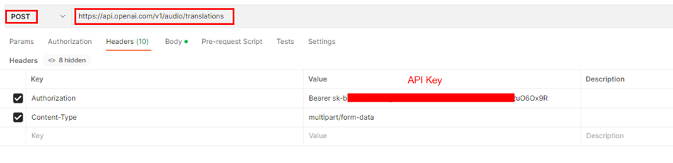
The speech to text API provides two endpoints, transcriptions and translations. At present, the maximum file size allowed for uploads is 25 MB and the supported audio formats are mp3, mp4, mpeg, mpga, m4a, wav, and webm. In this blog post, I utilized the Translation API to demonstrate its capability to convert English audio into text, it can understand other languages as well
If you have not yet created an API key, please sign up/login for OpenAI and obtain it from there.
Body:
Integration with Power Apps:
I have used a Power Automate flow with the Power Apps trigger to invoke the Speech to Text API via the HTTP connector in Power Automate. Alternatively, you can achieve the same outcome by constructing a Custom Connector. This sample app can be downloaded from this github link.
Microphone Control:
The audio control captures audio input through the device’s microphone and will be sent to the Power Automate flow for conversion into text using the Whisper API. The audio format of the recording depends on the type of device being used
3gp format for Android.
AAC format for iOS.
Webm format for web browsers.
I’ve tested this control from the app accessed through the web browser. If you encounter an unsupported audio format for OpenAI, you can use utilities such as FFMpeg. Additionally, a .Net version of the control is available for download which can be used in Azure Function. John Liu (MVP) has written a sample Azure function that handles the conversion of audio formats using the aforementioned utility.
Step 1: To add a microphone control to the canvas, insert the Microphone control from the command bar. To preview the recorded audio from the Microphone control, add an Audio control
Step 2: Add a button to convert and to trigger the Power Automate flow. Find below the Power FX code
//Generates a JSON Text with the binary of the Audio file or Recorded audio
Set(varJson,JSON(Microphone1.Audio,JSONFormat.IncludeBinaryData));
Set(strB64Audio, Last(Split(varJson, ",")).Value);
Set(strB64AudioContent, Left(strB64Audio, Len(strB64Audio) - 1));
//Extract Audio Format
Set(varAudioFileType,Mid(varJson,Find(":",varJson)+1,Find(";",varJson)-Find(":",varJson)-1));
//Call the Power Automate Flow
Set(audioText,'SpeechtoText-OpenAIWhisper'.Run(strB64AudioContent,varAudioFileType).audiotext);
The Power FX code performs the following task
Stores the audio captured by a Microphone control in a variable as JSON data, including binary data.
Extracts the base64-encoded audio content from the JSON data using the string manipulation functions Split, Left, Mid.
Determines the audio file type by parsing a string variable.
Uses the extracted audio content and file type to call the Power Automate flow ‘SpeechtoText-OpenAIWhisper’ to obtain the corresponding text transcription which comes in later section of this post.
Assigns the resulting text transcription to a variable named ‘audioText’, this is assigned to a Text Label to display the converted text from the OpenAI Whisper API.
Step 3: Add a Label control to display the converted Text set to the variable audioText
File Upload Control
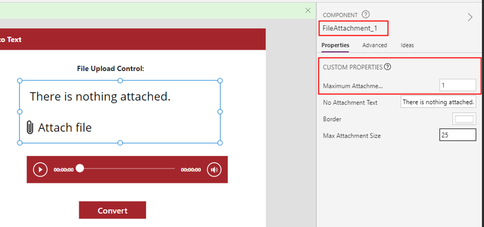
As of the day I am writing this post there is no file control that can handle all types of files in Power Apps, I have created a custom component utilizing the Attachment control to create a file attachment control. For further details, please refer to blogpost Uploading Files Made Easy: A Guide to Using the Attachment Control in Power Apps to add the control to the app.
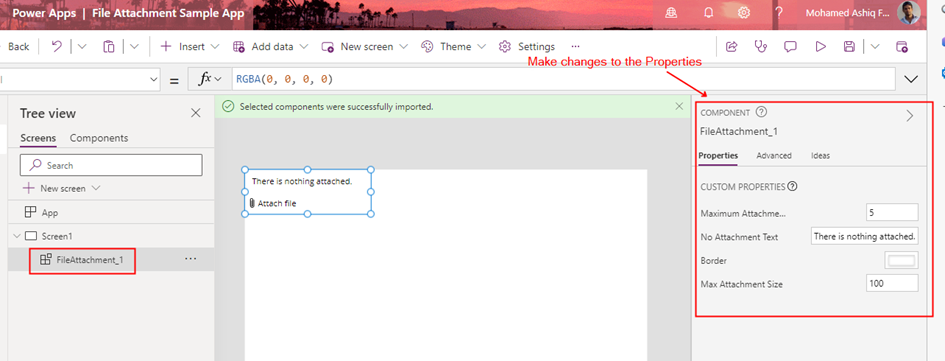
Step 1: Add the file attachment control to the app from the component library. Set the input property for Maximum Attachments to 1 from the component.
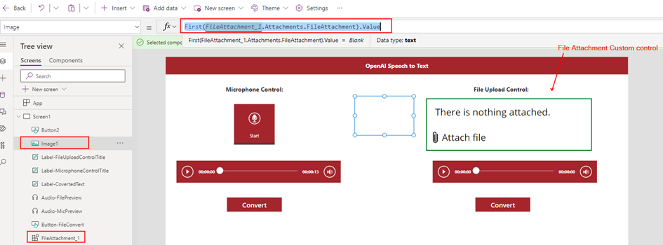
Step 2: To extract the binary content of an audio file, add an Image control to the app. The Image control is capable of working with any type of file to extract its content.
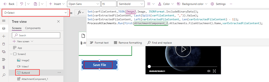
Step 3: Add a Button control to convert the Audio from the uploaded file. Find the PowerFX below
//Generates a JSON Text with the binary of the Audio file using the Image control
Set(varFileContent,JSON(Image1.Image,JSONFormat.IncludeBinaryData));
//Extract Base64 content
Set(varExtractedFileContent,Last(Split(varFileContent,",")).Value);
//Remove the last character " from the string
Set(varExtractedFileContent,Left(varExtractedFileContent,Len(varExtractedFileContent)-1));
//Extract Audio Format
Set(varAudioFileType,Mid(varFileContent,Find(":",varFileContent)+1,Find(";",varFileContent)-Find(":",varFileContent)-1));
//Call the Power Automate Flow
Set(audioText,'SpeechtoText-OpenAIWhisper'.Run(varExtractedFileContent,varAudioFileType).audiotext);
Step 4: Add a Label control to display the converted Text set to the variable audioText
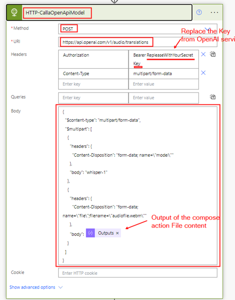
Power Automate Flow
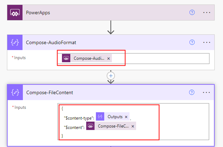
Now, let’s create a Power Automate flow with the Trigger type Power Apps to invoke the OpenAI Whisper API and convert speech to text. Step 1: Add two compose action (input parameters) to receive the audio format and content from either the recorded audio captured by the Microphone control or the uploaded audio file from the file attachment control in the Power Apps
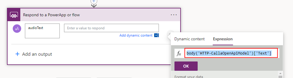
Step 3: Add the Respond to a PowerApp or a flow action to pass the converted text back to the app. To get the converted text, use the following expression
body('HTTP-CallaOpenApiModel')['Text']
The expression was constructed based on the response of the Whisper API call. In the event that the response property changes in the future, please ensure to update the expression accordingly.
Summary:
In this post, I’ve outlined a step-by-step guide on how to develop a basic app with Speech to Text functionality using Power Apps and a Power Automate flow leveraging the OpenAI’s Whisper API. The possibilities for using this technology are endless, from creating virtual assistants to generating audio captions and translations. Furthermore, the Whisper API can also be used to transcribe video files, adding even more versatility to its capabilities. It’s worth noting that while Azure offers its own Speech to Text service, it currently does not rely on the OpenAI Whisper Model. However, it’s possible that the two services will eventually integrate in the future. Hope you have found this informational & thanks for reading. If you are visiting my blog for the first time, please do look at my other blogposts.
Do you like this article?
Subscribe to my blog with your email address using the widget on the right side or on the bottom of this page to have new articles sent directly to your inbox the moment I publish them.
The Attachment control in Power Apps is a useful feature that allows users to upload and delete files, but it can only be used with data sources such as SharePoint List or Dataverse table. However, if you need to upload and delete files without using these data sources, you can create a custom component using the Attachment control or you can directly use this control in the app. I have followed the tip from Shane Young in this YouTube video to add the Attachment control to a component library.
By creating a custom component Library for the attachment control, you can upload and delete files similar to a Picture control but with the ability to handle any file type across any apps within an environment. This blog post is not a tutorial on how to create the component, but rather
How to use it
To Save the file in SharePoint Document Library using Power Automate Flow
How to customize the component to fit your needs.
How to use it – Add the Component to the Power Apps:
To incorporate this component into your app, you need to first import it into your environment. Please find below the steps to follow
Step 1: Download the component library from my github repo.
Step 2: Create a Blank Canvas App with a temporary name, on the studio command bar, click on the ellipsis > Click ‘Open’, browse to select the downloaded .msapp package. Save the App and then publish it. You would now be able to see the component from the Component Libraries.
Step 3: After following the instructions outlined in this documentation to import the Published component into your app, the component will be available for use in any app within the environment as shown below.
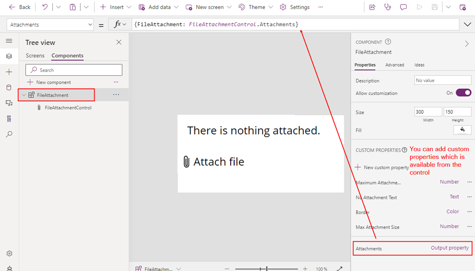
Step 4: Modify the input parameters of the component to adjust settings such as maximum number of attachments, border colour, attachment size, and other defined parameters of the component.
Step 5: To display the uploaded file content within the app or to send the file to a Power Automate flow, you can incorporate any of the following controls based on the file type:
The file content will be uploaded to the app as binary data with the URL appres://blobmanager/ for each file uploaded from the attachment control. To get the file Name:
Note: In the above screenshot, I have set the Max Attachments Component property to 1 in the Step 4
Send the File to Power Automate:
In order to send or store a file using a Power Automate flow, I needed to convert the file content to Base64 format. To accomplish this, I used a image control to capture the file content in binary format. Here is how I configured the image control:
This control works with any types of files to get the binary content.
After obtaining the binary content of the file using the JSON function, I performed some string manipulations to extract the binary content while excluding the Content-Type. Specifically, I used a combination of Split(), Left() and Last() functions to separate the content into an variable varExtractedFileContent.
By performing these manipulations, I was able to extract the binary content of the file in a format that could be easily passed to a Power Automate flow or other API or action.
This allowed me to send the file to a Power Automate flow, which could then save the file in a SharePoint library or call some other API or action that required the data to be in Base64 format.
The Power Automate flow used to save the file to a SharePoint Document Library is simple. The flow consists of a Power Apps trigger and a SharePoint action Create File, which takes two input parameters: File Name and File Content.
I have used the base64toBinary() expression to convert the base64-encoded string to binary data. This expression is a prerequisite for the SharePoint create file action and ensures that the file is saved correctly to the SharePoint Document Library.
If you need to upload multiple files to a library using the Attachment control, you can use Gallery control with the Image control, Collections, ForAll function, and the OnAddFile property from the Attachment control. First, create a collection to store the files that are uploaded using the Attachment control using the OnAddFile property. Then, use the Gallery control to load the binary of the uploaded files in the Image control. Next, use the ForAll function to iterate through each file in the gallery and call the Power Automate flow on a button click.
Customizing the Component:
The component I’ve created is a simple one for handling file attachments, but it does not have all the properties from the Attachment control. If you need more customization, you can easily modify it to suit your specific needs by adding additional input or output properties.
To add a new property, you can simply edit the component code and include the new property as an input or output parameter.
By customizing the component in this way, you can tailor it to your specific requirements and ensure that it meets all of your file attachment needs
Summary:
In summary, the Attachment control in Power Apps is a useful feature for uploading and deleting files, but it is limited to certain data sources. To work around this limitation, you can create a custom component using the Attachment control, which allows you to handle any file type and bypass the use of data sources like SharePoint or Dataverse tables. Hope you have found this informational & thanks for reading. If you are visiting my blog for the first time, please do look at my other blogposts.
Do you like this article?
Subscribe to my blog with your email address using the widget on the right side or on the bottom of this page to have new articles sent directly to your inbox the moment I publish them.