This post is in continuation to my journey with IoT leveraging Microsoft cloud services & it’s technology and based out of few questions I have been asked in few of the events I’ve spoken on the Topic Controlling Devices using Power Apps. In this post let us see how to turn on/off a LED connected to an Arduino UNO board by sending a message from Azure IoT hub or Power Apps with the help of a .NET core console application created from Visual studio code.
What is Arduino UNO Board:
Arduino Uno is an open-source & low cost microcontroller board based on Microchip ATmega328P microcontroller. The board is equipped with digital and analog Input/Output pins that can be interfaced with other circuits. If there is a need to collect data from sensors (Temperature, Humidity etc) then the mode of the pin should be Input and for controlling devices or activating relays the pin mode must be Output. For this example since we will have to turn on/off a LED, the pin mode has to set as Output.
Arduino IDE:
The IDE is a cross platform application written using C++. If you have worked with an Arduino board already, you would have probably used the Arduino IDE to deploy code called as Sketch. The code written on the sketch is compiled to a HEX file (Machine language) which can be understood by the microcontroller once the sketch is uploaded. The hex file is then sent to the Arduino UNO board using the USB port.
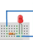
Find below the design with information on the different components used:
Azure IoT Hub:
IoT hub is a managed service hosted in cloud that acts as a central message hub for bi-directional communication from the device to the cloud and the cloud to the device. There is an also a Free-Tier limited to one per subscription which can add up to 500 devices and 8000 msgs/day as of today based on the Pricing calculator. Create a IoT Hub for us to send a message to the Arduino UNO device as per the instruction given in the article. After the IoT hub is created.
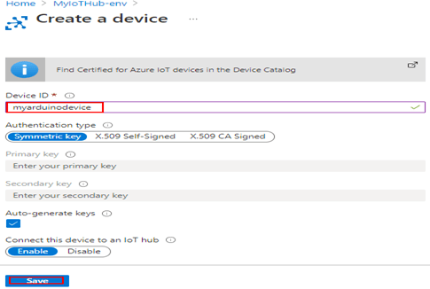
A device must be registered with your IoT hub before it can connect. There are different ways to register a device like using Azure Cloud shell, in this case we will use portal. Click IoT Devices under the Explorers blade on the IoT hub and click on + New, enter the Device ID and click save.
Copy the Primary key of the registered device
Copy the Hostname from the IoT Hub Overview blade
These values will be used later in the .NET console application
Arduino Sketch:
Let us now create a simple Arduino project sketch from Visual studio code to send signal to Arduino Board using the serial port with the help of the Nuget package System.IO.Ports. Make sure the Arduino IDE and the Arduino extension for VS code is installed. The Arduino board can now be plugged in to the USB port of your laptop or computer with the provided cable. Follow the below mentioned steps to create an Arduino sketch template from VS Code
Create a folder on the development machine for the Arduino project and then open the folder in Visual Studio code
In VS Code, hit the key CTRL+Shift+P to open the command pallete
Type the command Arduino: Initialize which will try to create a file with name app.ino. Change the name of the file relevant to your project. I have named it as ControlDevicesforCSharp.ino.
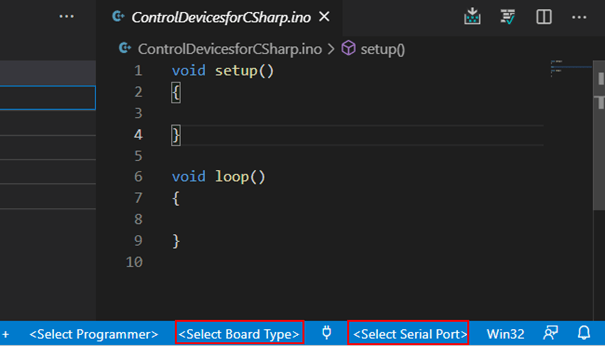
You will now be prompted to select the name of the Arduino board. I have selected Arduino UNO. You can also select the board and port from the VS Code right bottom corner as shown below
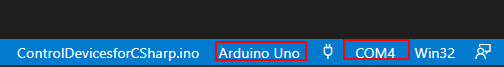
The serial port will be visible if the board in plugged in and recognized by the computer. This is how it looks after the board and the port is selected.
Now update the code as shown below to receive signal from the console application. If it receives a value of A to the character variable inputValue from the console application, then the PIN 13 is set to HIGH which means it generates 5v as an output and if the inputValue is B the PIN 13 is set to LOW which means the Output of the pin will be zero as opposed to 5v when set to HIGH. If you want, you can connect a LED to the PIN 13 with a 220 ohm resistor bu the pin 13 has a in-built LED to test. You can also notice on the code the PIN mode for 13 is set to Output.
#define BaudRate 9600

char inputValue;
int led1 = 13;

void setup() {
  // Initialize serial communication at 9600 bits per second
  Serial.begin(BaudRate);
  // Prepare the digital output pins
  pinMode(led1, OUTPUT);
  // Initially all are off
  digitalWrite(led1, LOW);
}

// the loop function runs over and over again forever
void loop()
{
  // Reads the input
  inputValue = Serial.read();
  if(inputValue == 'A')
  {
    // Turn on the LED
    digitalWrite(led1, HIGH);
  }
  else if (inputValue == 'B')
  {
    // Turn off the LED
    digitalWrite(led1, LOW);
  }
}
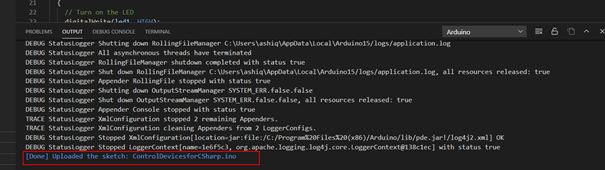
Now you verify the sketch by pressing CTRL+AL+R if there is any compile error. If all is well, you can now upload the sketch by pressing the key CTRL+ALT+U. If the upload is successful, you will the following message on the VS output terminal
Now the sketch is ready, it is now time to create the console application to receive message from Azure IoT hub to control the LED from cloud applications like Power Apps.
.NET core console Application:
The package System.IO.Ports supports to control serial ports which will be used to send message to Arduino board (A or B) to turn on or off the LED. Follow the below given steps to create the console application
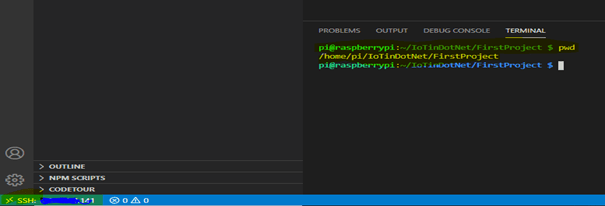
Use the same directory you have used to create the Arduino sketch. On the VS Code terminal window, enter the command dotnet new console to create a new console application
Add the package System.IO.Ports using the nuget package manager plugin by CTRL+SHIFT+P > NuGet Package Manager: Add Package or enter the command on the terminal window dotnet add package System.IO.Ports –version 6.0.0-preview.1.21102.12
Method Encoding.ASCII.GetString(receivedMessage.GetBytes()) reads the message
Method deviceClient.CompleteAsync(receivedMessage, _ct) deletes the message from the queue
The following code establishes the connection on the serial port COM4
// Initialises the serial port communication on COM4
SerialPort = new SerialPort("COM4")
{
                BaudRate = 9600,
                Parity = Parity.None,
                StopBits = StopBits.One,
                DataBits = 8,
                Handshake = Handshake.None
};
// Subscribe to the event
SerialPort.DataReceived += SerialPortDataReceived;
// Now open the port.
SerialPort.Open();
With the help of the following method to Subscribe
static void SerialPortDataReceived(object sender, SerialDataReceivedEventArgs e)
{
 var serialPort = (SerialPort)sender;
 // Read the data that's in the serial buffer.
 var serialdata = serialPort.ReadExisting();
}
The code SerialPort.Write(“A”) send the message to the Arduino Sketch.
Now run the dotnet application using the command dotnet run. Now send a message from the Azure IoT explorer or from Azure portal IoT device explorer ON1 or Off1 to turn On/Off the LED connected to PIN 13
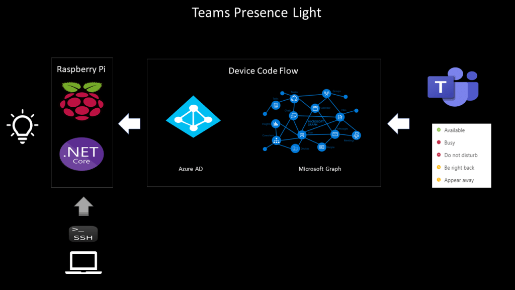
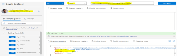
Almost every one of us is working from home these days due to the Corono situation we are in as of the time I am writing this article. I wrote a recent blog post about controlling devices from PowerApps with the help of a Raspberry PI and thought of extending the project by creating a Teams presence light with the help of a Raspberry Pi & couple of LED’s with different colours. This was possible due to the availability of the presence API endpoint in MS Graph, this helps us get the user’s current team presence (Available, Busy, Be right back, Do not disturb etc) for a logged in user. As of the time I am writing this article application permissions are not supported.
Device Code Flow:
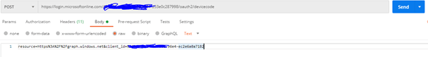
The supported permission type is Delegated to get the presence information in MS graph, the user must sign in to get the users Teams presence. So how can a user signin/authenticate on a device like Raspberry Pi if we are only using a Terminal window to develop & run the application which I will doing it here, Device code flow to the rescue which is an authentication flow to get the data from MS graph for handling delegated permissions with remote signin/authentication using an auto generated device code. This flow lets the user use another device (for instance the windows client with the VS Code) to sign-in interactively. By using the device code flow, the application obtains tokens through a two-step process especially designed for these devices like Raspberry Pi. Examples of such applications are applications running on iOT, or Command-Line tools (CLI).
Refer this blog post for the steps & instructions to develop applications remotely on a Raspberry Pi using VS code.
Application Design:
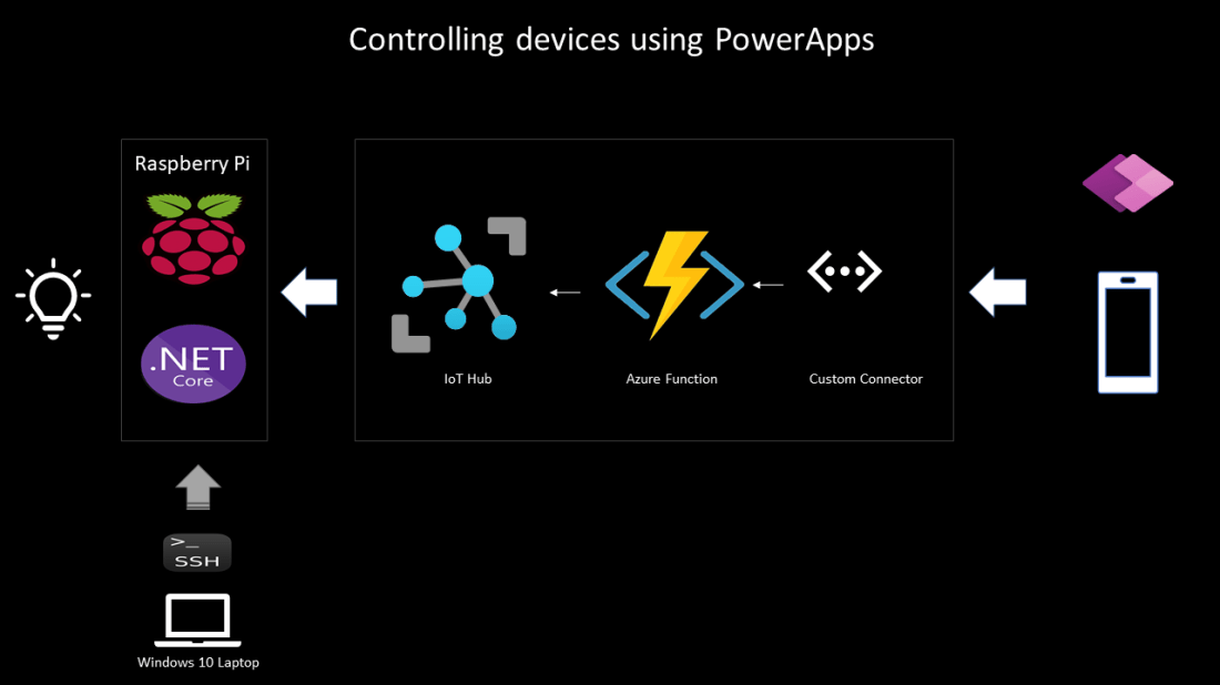
There will be a .NET core console application polling the MS Graph presence endpoint every 5 seconds and based on the status, the corresponding coloured lights will be turned on. Find below the high-level design of the application
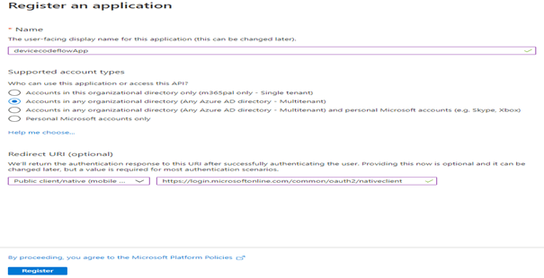
Active Directory application registration:
Start with registering an Application in Active directory with the following settings
Supported Account Types: Accounts in any organizational directory
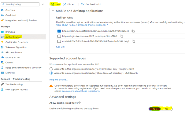
Enable Allow public client flows a required setting for the device code flow to work as shown below
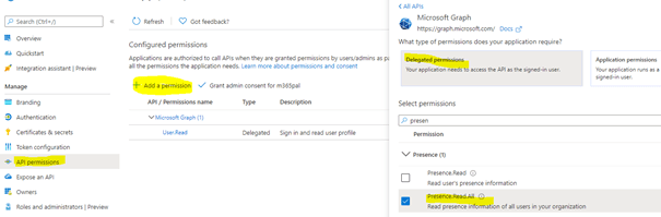
Add the permission Presence.Read.All if you going to create a presence light for some other user other than the signed in user and Presence.Read if its going to be only for the signed in user. Once the permission is added, grant admin consent.
In this example, GPIO pins 12 and 13 are used with Green and Red LED’s but you can also use a RGB LED matrix supported for Raspberry Pi which are readily available in the market. Use the Client Id and the tenant id of the application in the app.
Provide the GPIO pins the root permissions through the command on the terminal window /usr/bin/gpio export 12 out and /usr/bin/gpio export 13 out.
Run the application by using dotnet run
Method AcquireByDeviceCodeAsync(IPublicClientApplication pca) generates the device code
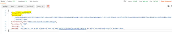
As soon as the application is run from the command line, the code is generated as shown below
Code pca.AcquireTokenSilent(Scopes, accounts.FirstOrDefault()).ExecuteAsync(); generates the token which will used along with the graph GET request for getting the teams presence status of the user
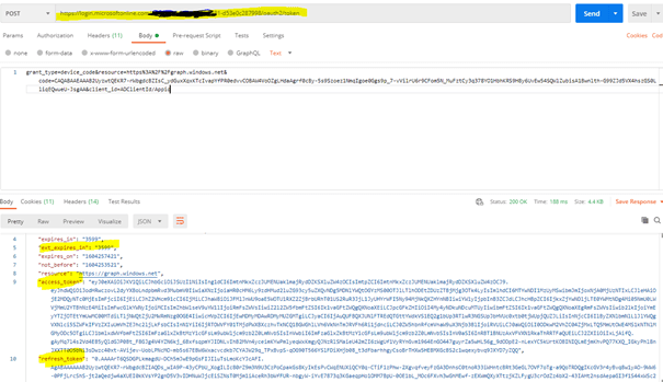
The Token will be valid only for 3599 seconds which is close to 1 hour. Generate one more token using the same line of code after an hour which I have not handled in the sample code.
Polling will happen every 5 seconds using the .NET Timer_timer.Change(TimeSpan.FromSeconds(0), TimeSpan.FromSeconds(5));
Based on the teams presence, the corresponding lights will be turned on using the below code
switch (presenceStatus)
{
                        case "Available":
                            Console.WriteLine($"{DateTime.Now} : User is Available");
                            controller.Write(pinGreen, PinValue.High);
                            controller.Write(pinRed, PinValue.Low);
                            break;
                        case "Busy":
                            Console.WriteLine($"{DateTime.Now} : User is Busy");
                            controller.Write(pinGreen, PinValue.Low);
                            controller.Write(pinRed, PinValue.High);
                            break;
}
Code for this application can be found in this GitHub repo link.
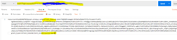
Request Body: grant_type=device_code&resource=https%3A%2F%2Fgraph.windows.net&code=CAQABAAEAAAB2UyzwtQEKR7-rWbgdcBZIsC_ydGuxXqxKTcIvapYfPR0edvvCOBAW4VoOZgLHdaAgrf0cBy-5s9Szoez1NmqIgoe0Ggs9p_7-vVilrU6r9CFom5N_M(Information from the Previous response)&client_id= ADClientId/Appid
Will generate the token in the response
Refresh Token:
This token is used to generate access token after the initial one expires by making another request with information like this in the request body
All of these are handled for us by the Microsoft Authentication library for .NET.
Summary: I’ve used MSAL for .NET library but there are also libraries for MSAL for Python and for other languages as well based on your comfort with the programming language. Hope you have found this informational & interesting. Let me know any feedback or comments on the comment section below
I have recently purchased a Raspberry Pi 4 to explore IoT with Microsoft 365 platform. The Raspberry Pi is a low-cost credit-card sized computer which can be connected to a monitor, keyboard, mouse and to Internet via Wi-Fi or ethernet port. In addition, the Raspberry Pi has a 40 pin GPIO (General Purpose I/O) connector for us to connect sensors (Input) and to control devices (Output) through a relay. It enables people of all ages to explore computing and to learn how to program in languages like Scratch, Python, .NET core etc. One of the most popular operating system for the Raspberry Pi is Raspbian which is also the official one but there are also other operating systems like Ubuntu, Windows 10 IoT core (Not supported for Raspberry Pi 4). On this blog post, I will cover the different components used to integrate Raspberry Pi with Microsoft 365 service PowerApps & Azure services like Azure functions & Azure IoT hub to control devices. Find below the design and the different components used
Environment Setup
Raspberry Pi setup for IoT with .NET Core
Visual Studio Code setup for remote development
Azure IoT hub
.NET Core Console Application
Azure Function – HTTP Trigger
Power Apps
Custom Connector
Canvas Apps
Environment Setup:
Raspbian OS is based on the Debain Operating System which has been optimized for Raspberry Pi hardware and it is the official one. You can find here some instructional videos on the following link to the install the OS on your Raspberry Pi
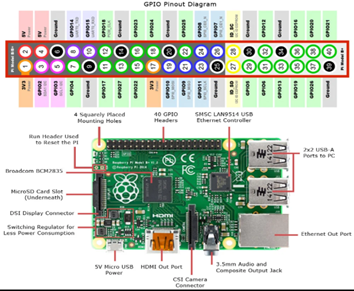
If you have ordered a Raspberry Pi with a starter kit, most of the sellers would have loaded the Raspbian OS image on the SD card as a part of the kit. Once the OS is installed & configured, it is ready for use with the default username pi and the password is raspberry. Find below the schematic and the GPIO pin out diagram. On the sample code I have used Pin 17 and Pin 18 to control devices
Remote Tools:
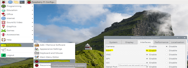
There are tools to connect raspberry Pi remotely from your Windows client. Software xrdp provides a graphical interface for the users to remotely connect Raspberry Pi using Microsoft’s RDP mstsc.exe. Follow along this blogpost to set this up on the Raspberry Pi to enable remote connectivity. You can also use PuTTY a SSH tool to remotely connect with Raspberry Pi device. To know the IP address of the device, login to the Router to which the raspberry pi is connected or through the command hostname -I on the command line. To use PuTTY client & VS Code remote development plugin, SSH must be enabled on the Raspberry Pi OS. By default, it is disabled to enable follow the below steps
Launch Raspberry Pi Configuration from the Preferences menu.
Navigate to the Interfaces tab.
Select Enabled next to SSH.
Click OK
Raspberry Pi Setup for IoT with .NET Core:
.NET core is an open source development platform maintained by Microsoft and .NET community on Github. I have chosen .Net core and the programming language C# in which I am comfortable with. There are also python libraries to control GPIO pins in Raspberry Pi. To use .NET core IoT librariesinstall .NET core 3.1 on Raspberry Pi. Follow the instructions below to install .NET core
Copy the Direct link of the .NET core SDK from the link for Linux ARM32. Based on information gathered from few blogposts .NET core is supported for ARM64 though Raspberry Pi is 64 bit. Get the latest link from https://dotnet.microsoft.com/download/dotnet-core/3.1
Open a Terminal window in Raspberry Pi. Enter the following command to download the .Net core sdk binary
To make it available permanently on all the sessions. Run the following command to open the .profile file to save the information
sudo nano .profile
Add the following lines at the end of the file by scrolling and then save it (CTRL+S) and then exit using (CTRL+X)
# set .NET Core SDK and Runtime path
export DOTNET_ROOT=$HOME/dotnet
export PATH=$PATH:$HOME/dotnet
Run the command dotnet –info to know the version of the .Net core
Visual Studio Code setup for remote development:
You can develop applications remotely on a Raspberry Pi device using VS Code with the help of a plugin Remote Development which uses SSH to connect. After the plugin in installed, perform the following steps to remotely connect the Raspberry Pi device
Have the IP address of the Raspberry Device ready which will be used to add a SSH host. Use the command hostname -I on the Raspberry Pi’s terminal window will reveal the IP address
Go to the VS code and press CTRL+SHIFT+P together and type Remote-SSH: Connect to Host & select
Click Add New SSH Host
Type ssh pi@x.x.x.x -A and then press Enter. X.X.X.X is the IP address of your raspberry device and pi is the username (Default)
Select the configuration file. I have used default, %USERPROFILE%\.ssh\config on Windows 10
Host will be added. You are now ready to connect remotely provided the SSH is enabled on the Raspberry Pi.
Azure IoT Hub:
IoT hub is a managed service hosted in cloud that acts as a central message hub for bi-directional communication from the device to the cloud and the cloud to the device. There is a also a Free-Tier limited to one per subscription which can add up to 500 devices and 8000 msgs/day as of today based on the Pricing calculator. Go through the Microsoft documentation about IoT hub. Create a IoT Hub for us to send a message to the Raspberry Pi device for us control the device as per the instruction given in this article. After the IoT hub is created
A device must be registered with your IoT hub before it can connect. There are different ways to register a device like using Azure Cloud shell, in this case we will use portal. Click IoT Devices under the Explorers blade on the IoT hub and click on + New, enter the Device ID and click save.
Copy the Primary key of the registered device
Copy the Hostname from the IoT Hub Overview blade
These values will be used later in the .NET console application
Device Explorer:
It is a tool which helps you to manage devices by connecting to the IoT hub you have just created, it can be also done from the Azure portal, Azure Cli etc. It is very easy to connect to the IoT hub using the connection string. Download the device explorer from the https://aka.ms/aziotdevexp
To get the connection string, click Shared access policies under Settings blade and click iothubowner policy. Copy the Connection string-primary key and paste it on the Configuration section of the Device explorer and click Update as shown below
To send a message to the device click the tab Messages to Device and for registering new devices click Management.
.NET Core Console Application:
The Microsoft .NET core team also has a .NET core IoT library. The package System.Device.Gpio supports GPIO pins to control sensors (Pin Mode: Input) and devices like relay, LED’s (Pin Mode: Output). In this case we will be using the Pin no 17 & 18 to turn on or off a LED with Pin mode set as Output.
Setup for controlling devices:
To control a LED, connect a 220 ohm resistor to the long lead and the other end to a GPIO Pin (17 & 18) & the short LED lead to any one of the GPIO Ground.
In my setup I have used a Breadboard, GPIO Extension board & GPIO extension cable. GPIO Pin’s 17 & 18 are used, there are many other pins for us to use. Look at the GPIO pin schematics for more details on the pins. There are also relays designed for Raspberry Pi which helps controlling real devices, there are different relays module (4 channel, 8 channel, 10 channel etc) available in the market.
Connect Remotely to Raspberry Pi using VS code:
Connect the VS code to the Raspberry Pi using SSH by using keyboard shortcut CTRL+SHIFT+P and click Remote-SSH: Connect to Host and click the IP of the raspberry PI or the hostname based on the VS code setup (SSH Host) we have done earlier
After the password (Default: raspberry) is entered. If you see on the left bottom corner of the VS code with SSH: IP Address or host name, it is then successfully connected
In the terminal window you can enter all bash commands in context of Raspberry Pi.
VS Code Plugin:
To add a package from VS code to the Console app project install a plugin Nuget Packet manager. You can also use the CLI command on the terminal window to add the package but the plugin will help us to add different packages using the UI. All the packages will be installed on Raspberry Pi device as shown below
I also recommend you install to C# and CodeTour extensions (code walkthrough for the code I’ve used for this sample project).
Create the first Console Application to control a LED:
Follow the below steps to control a LED connected to GPIO PIN 22 using the .NET IoT package System.Device.Gpio
On the VS Code terminal window, enter the command dotnet new console to create a new console application
Add the package System.Device.Gpio using the nuget package manager plugin by CTRL+SHIFT+P > NuGet Package Manager: Add Package
Add the following code to the Program.cs file
using System;
using System.Device.Gpio;

namespace DemoProject-GPIOControl
{
    class Program
    {
        static void Main(string[] args)
        {
            Console.WriteLine("Turning on Light from Pin 22");
            using var controller = new GpioController();
            controller.OpenPin(22, PinMode.Output);
            controller.Write(22, PinValue.High);
            Console.ReadKey();

        }
    }
}
Run the command on the Terminal window dotnet run. There will be an unauthorized exception as below
Unhandled exception. System.UnauthorizedAccessException: Setting a mode to a pin requires root permissions.
 ---> System.UnauthorizedAccessException: Access to the path '/sys/class/gpio/gpio17/direction' is denied.
 ---> System.IO.IOException: Permission denied
Enter the following command on the terminal window to provide root permission for Pin no 22: /usr/bin/gpio export 22 out. This command has to be executed everytime you restart the Raspberry Pi unless you provide root permissions to the account which could be done by setting a value on the root configuration file.
Now run the dotnet console app using the command dotnet run which will turn on the LED light connected to PIN 22. The output voltage on PIN will be 3.2 volt if the pinvalue is set to High and will be Zero if its set to Low.
Code controller.Write(22, PinValue.Low); will turn off the light
To remotely debug on the Linux Arm, follow the instruction on this article.
To disconnect in VS code, click File > Close Remote Connection
Method Encoding.ASCII.GetString(receivedMessage.GetBytes()) reads the message
Method deviceClient.CompleteAsync(receivedMessage, _ct) deletes the message from the queue
Do not forget to run the commands /usr/bin/gpio export 17 out and /usr/bin/gpio export 18 out based on the pins you are controlling. Then run the dotnet application using the command dotnet run. Now send a message from the Device explorer or from Azure portal IoT device explorer ON1 or Off1 to turn On/Off the LED connected to PIN 17 and ON2 or Off2 to turn On/Off the LED connected to PIN 18.
On this example we have used Cloud to device messages which sends a one way notification but you can also use Direct Methods & Device Twin to control devices, go through the following documentation from Microsoft with guidance to send cloud to device communications using different methods
Find here the sample of the console application from GitHub. Now the console application is ready, let us create the Azure Function app to use it in the PowerApps.
Azure Function App – HTTP Trigger:
I’ve used a Consumption plan Function app which gets triggered on a HTTP request to send a message to IoT hub registered device using the method ServiceClient.SendAsync from the package Microsoft.Azure.Devices to send a one way notification to the registered Raspberry Pi device. The message will be sent to the device on the HTTP request as query string (Parameter name: name)
Create a Function App from the Visual Studio 2019, I’ve used VS 2019 but you can also use VS Code
Add the HTTP trigger with authorization Level of the Function App as Function
Add the Nuget Package Microsoft.Azure.Devices
Have the connection string handy for the iothubowner policy used on the device explorer.
Copy the following Code:
 using System;
 using System.IO;
 using System.Threading.Tasks;
 using Microsoft.AspNetCore.Mvc;
 using Microsoft.Azure.WebJobs;
 using Microsoft.Azure.WebJobs.Extensions.Http;
 using Microsoft.AspNetCore.Http;
 using Microsoft.Extensions.Logging;
 using Newtonsoft.Json;
 using Microsoft.Azure.Devices;
 using System.Text;
 using System.Net;

 namespace FunctionApp_IoT
 {
     public static class Function1
     {
         static ServiceClient serviceClient;
         static string connectionString = "HostName=YourIoTHub-env.azure-devices.net;SharedAccessKeyName=iothubowner;SharedAccessKey=Yourkey";
         static string targetDevice = "Your Device ID";
         [FunctionName("Function1")]
         public static IActionResult Run(
             [HttpTrigger(AuthorizationLevel.Function, "get", "post", Route = null)] HttpRequest req,
             ILogger log)
         {
             log.LogInformation("C# HTTP trigger function processed a request.");

             string name = req.Query["name"];

             serviceClient = ServiceClient.CreateFromConnectionString(connectionString);

             SendCloudToDeviceMessageAsync(name).Wait();

             return new OkObjectResult(new { status = "Light turned On or Off" });

         }
         private async static Task SendCloudToDeviceMessageAsync(string condition)
         {
             var commandMessage = new
              Message(Encoding.ASCII.GetBytes(condition));
             await serviceClient.SendAsync(targetDevice, commandMessage);
         }
     }

 }
Publish the function app to Azure. Test it by sending HTTP requests using Postman tool or browser. The function API is ready, we are now ready to call the function in PowerApps
So far we have progressed till a HTTP API endpoint using serverless which sends a message to the Raspberry Pi through the IoT hub, if we have to call this API on PowerApps we will have to create a custom connector which allows you to connect to any RESTful API endpoint. Bear in mind that to use a PowerApp which has a custom connector, the users should have a premium license.
Custom Connector:
Let us go ahead and create the custom connector, you can find here on the GitHub repo for the swagger definition file for creating the custom connector. Download the file and go to your Power Platform environment and click to the Custom Connectors link under Data.
Click the Import an OpenAPI file under New custom connector and import the Swagger definition file you have downloaded from the repo
Once it is imported, change the host on the General tab based on the function app URL and the Security will have authentication type as API Key and on the Definition tab there will be one action which be called from the PowerApps to control devices. After the settings are configured you can create the connector by clicking the link Create connector. You can test the connector by creating the connection by passing in the Code parameter of the function app and pass the message to test the operation. Make sure the console app is running in order to receive the message & to turn on/off the device.
PowerApps Canvas App:
Once the custom connector is created you can use it on the PowerApps canvas app by creating a connection to the connector like below
After the connection is created and added on the app, you can use on the PowerApps controls like Toggle, button etc to turn on/off the devices using the code ‘IOT-ControlDevice’.ControlDevice({name: “on1”}) / ‘IOT-ControlDevice’.ControlDevice({name: “off1”}). If a toggle control is used, the code will be something like this
Voila, now you were able to control devices from PowerApps.
Summary: On this post we have seen how to integrate Azure IoT with PowerApps and to control devices through a PowerApps. This is just a sample, you can extend this example based on your needs. Hope you have found this informational & interesting. Let me know any feedback or comments on the comment section below